
|
|
|
Lucent Range Extender to Outdoor Omni Conversion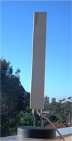 Subtitled: Making a Semi-Respectable Omnidirectional Vertical from a Lucent / Wavelan / Enterasys / Cabletron / Compaq / Avaya Range Extender
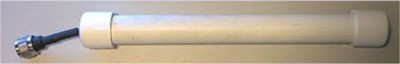
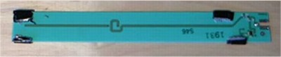
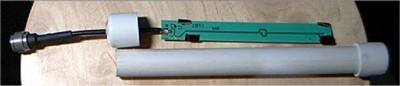
The range extender is a 2 element collinear built on a very thin PCB, mounted in a non-weatherproof case on a heavy rubber base. It has a very long and lossy thin coax feed, designed to both attenuate the signal and provide some flexibility in placement.
A full description of the antenna can be found at http://devices.planet-wireless.de/reant/ Backgrounder After recently moving to South Perth and with a great link to HillsHub, arguably the main freenet node, rampant altruism took me over and I decided to setup a public freenet access point.Ā I'm located on the top of a hill, and anticipate that there will be people below me in South Perth, as well as people across the river in Nedlands who will be after freenet access on my AP.Ā
I therefore had a requirement for a relatively low gain, wide lobed omni, on a different polarisation from the main freenet access points in the hills surrounding Perth, and obviously a preference for low cost.
I'd managed to procure a Range Extender for nothing because it had a munted (folded over centre pin) Lucent connector on the end of it.Ā I'd had a good play with one before, shoved an N-type on it, went stumbling, got rather bored, and decided it'd be better re-deployed on my roof.
The gain of the antenna, exclusive of cable loss, is supposedly 6dbi - could somebody do the maths and figure out what it for me please? Foregrounder OK, so how did I convert this indoor antenna into a decently performing outdoor?
Ingredients:
From Bunnings / Hardware: From Elsewhere:
Tools:
Method: Combine ingredients.Ā No I'm kidding, but if you've looked at the pictures, you've probably already got it sussed out.
Step 1 - Naked Bits. De-case the lucent range extender until you end up with this:
Turn the range extender's base into a handy soldering iron holder, so you dont burn yourself on...
Step 3 - Almost free pigtail, maybe. Un solder the original pigtail from the antenna. You can now convert this pigtail into a real life pigtail by purchasing a clamp type RG316(?) N-type from WACB.Ā Cost runs to about a tenner, fairly decent considering. I didnt do this, because my lucent connector was broken, remember? Step 4 - Cut + Fit Gaffer Tape. Layer 5 pieces of gaffer tape on top of each other, then cut into small rectangles. Place the rectangles at the extremities of the antenna as pictured. These are to centre the PCB inside the tube and provide some mechanical resistance as you slide it in and line it up while the silicon dries. Depending upon your tape, you may need more or less than 5 layers of tape, ensure that there's a good resistance fit inside the tube Step 6 - Drill Endcap. Take your drill and using a centre punch, or by giving the drill a good whack, ensure that you get the hole in roughly the centre of the endcap.Ā My Iplex ones didnt have an impression (they had a raised bump!Ā bastards!), so I took it slowly and purchased a few extras to be sure.
Cut off at least 25cm of PVC pipe, ensure that there's enough clearance for the PCB inside, see Important Things to Note part 2 below
Step 8 - Solder Pigtail to PCB thru Endcap. Self explanatory, make sure you have enough length to push PCB up, as well as get a cable tie around the cable to provide strain relief.Ā Then fit the cable tie to the inside.
Step 9 - Prep surfaces and glue. Read your glue bottle, and prep the surfaces and glue the two endcaps on.Ā You may want to be pre-emptive with some silicon on the RG58 to be doubly sure.Ā If you're totally anal, put some silica gel in to soak up any moisture that may already be inside, or make it's way inside.Ā Alternatively, dont build this antenna if you're in a temporate climate. Step 10 - Put a cable tie on the bottom of the RG58 to provide strain relief. Just do it, ok
Step 11 - Silicon the Buggery out of it. Apply a bead of silicon around all cracks, and a massive gob of silicon on the bottom of the antenna around where the cable comes out.
Important things to note: 1: Make the shaft of the antenna long, with the PCB located towards the top of the shaft, so that any mounting work you do at the bottom of the shaft wont have an effect on performance.
2: Ensure that the top and bottom edges of the PCB finish inside the tube above and below the point where the endcaps cover the tube - the PVC -does- attenuate the signal, and the less it has to go through the better. Wossit look like?
So how's it perform?
Quick empirical test from 3.5km away (across to nedlands) proved -very- promising.Ā Some netstumbler graphs will be provided as and when, but suffice to say, it's quite reasonable for the price!
I've looked for some el/az plots of the antenna's performance, but i've not found any (bastard manufacturers) - I think it's fairly safe to assume it's quite lobey though, and it's characteristics wouldnt have changed much from the original design, perhaps unless you've mounted it's shaft very close to some metal. | links Innaloo.net Main Page email me |
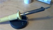 Step 2 - Free soldering Iron Holder.
 Step 7 - Hacksaw shaft.